nRF network and Node-red
This project was done by G. K. Sriharsha. His project report can be found here.
Goal
The goal of this project is to design a wireless sensor network that uses nRFL2401 as radio module and communicates through MQTT protocol.
Getting started
For this project, we will be needing the following hardware and software
| Hardware | Software |
| Raspberry Pi (Model 3B) – 1 no | Arduino IDE |
| Arduino UNO (V3) – 2 nos | Python |
| nRF24l01 radio modules – 3 nos | Mosquitto |
| DHT 11/22 – 2 nos | RF24Network library |
| LDR – 2 nos | Node-red |
| PIR – 2 nos |
A Customized network – A simple RF communication
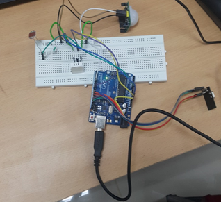
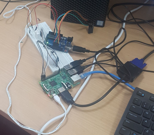
In this network, there are only two sensor nodes. This is designed as a ‘‘two-place" system. One node will be deployed outdoor with a power connection from a battery while the other node is kept inside connected to a wall socket. In this setup, there are two Arduinos and one Raspberry Pi. The Arduino used in the indoor deployment (master Arduino) is connected to Raspberry Pi via USB connection. The data transfer between the master Arduino and the Raspberry Pi is via Serial communication. The other Arduino, deployed outdoor (slave Arduino) communicates using the NRF board to the master Arduino which in turn forwards the data to the Raspberry Pi via USB.

Since the Raspberry Pi does not have ADC support, LDR and other analog sensors must be connected to master Arduino. The python script is written such that it will signal the master Arduino to measure the analog value and send the data.The rest of the sensors (digital input/output) are connected to Raspberry Pi to reduce the load on Arduino.
The functions of Python script in Raspberry Pi are
-
To check,correct and update (if necessary) the timing interval of the slave Arduino
-
Signal the master Arduino for the sensor data
-
item Logging the sensor data into different files according to the type of measurement. (Computational and Non- computational)
Execution of Python script in Raspberry Pi
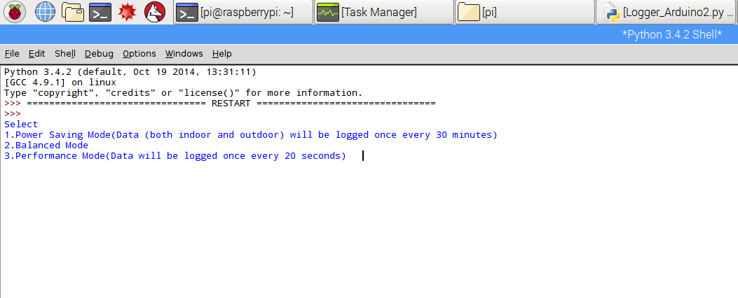
Raspberry Pi has a Python script, running mainly for the above mentioned reasons. At the start of the execution, it asks user for the input.The user gets to choose among three modes.
-
Power Saving Mode - Once every 30 minutes, the sensor data is updated
-
Balanced Mode - The user can set the update intervals of the nodes separately, with a value between 3 seconds to 30 minutes.
-
Aggressive Mode - The nodes will be updating the data once every 20 seconds.
The slave node executes a code which keeps it in one of the two states. It is either listening constantly for an interrupt of its routine interval or it is transmitting the data at the end of the previously said interval.When a command is received, it will be in effect from next measurement.
The Python code has a variable to keep in track of the measurement interval. It is an array of two numbers. The latest time (in milliseconds) is stored in the place of the older of the two times present. The difference of the two blocks gives the delay time of the two successive sensor data. If this is not equal to the interval which the user has set (within a margin of error), then the Python re-instructs the master node to set the selected interval for the slave node.The indoor part of the measurements happen from the Raspberry Pi itself, hence there is no need for keeping it in synchronization. A simple time tracker is enough to keep the measurement interval to a particular interval.
Whenever the state of PIR sensor in slave node goes HIGH, then the listening stops and transmits a code which the master Arduino understands as an interrupt and can distinguish this from data. Master Arduino forwards this message to the Raspberry Pi after attaching the slave node address via USB. If there is a HIGH state for PIR attached to Raspberry Pi, then the message is directly logged with Raspberry Pi's address.If it is time for indoor measurement, the script sends a code which the master Arduino can decipher to be the request for LDR value. After measuring the LDR value, it is transmitted back via the same Serial connection.In this way the sensors are used to get the values for indoor and outdoor weather parameters.
Advantages of this customized system
-
It is best for small environments
-
Small payload size because there wont be a field for node address ,etc.
-
Easy to control and debug the system.
Disadvantages of this customized system
-
Interoperability and heterogeneous nature is lacking ,i.e, a board with ESP communication board cannot be a part of the network
-
Actuation network cannot be created because of lack of interoperability.
-
There is no uniformity in message structure and communication.
A Standardized solution – A structured network with MQTT
In order to counter the limitations of the previous network, a standardized approach is necessary to level out all the differences in nodes and their various modes of communication.In this solution, the Raspberry Pi is interfaced with NRF radio directly and a network is formed with it as a parent and the other Arduinos as children.This network is called RF24SN. This network is responsible for the reception of data from Arduino sensor node to Raspberry Pi.
Once the data is received into Raspberry Pi, it then published into an MQTT broker program running in the background. In this setup we have used open source software Mosquitto and its API to publish and subscribe data from the C script running in the Raspberry Pi. If a message is published in the topic of subscription, the C code is programmed to send an appropriate message to the nodes. For example, if a message is published into “SettingsKnode1Interval” with 20 , then the interval of Node1 is set to 20 seconds by sending an appropriate message. In a similar way, a switch is programmed such that an individual measurement is turned off/on by publishing the message under the appropriate channel. For data interoperability, before publishing the data, it is converted into JSON format. This is done to all data coming into the MQTT server to maintain uniformity in the network.
From the perspective of the MQTT broker, it is all about data being published and being re-routed to interested nodes. Due to a common JSON format, MQTT broker can directly send the data to the actuator node which can read the information after processing it.To the same MQTT broker,data from other nodes are published. The Raspberry Pi is configured in a way, to receive data from all kinds of radios available. It is at this level, all of the network converges to.
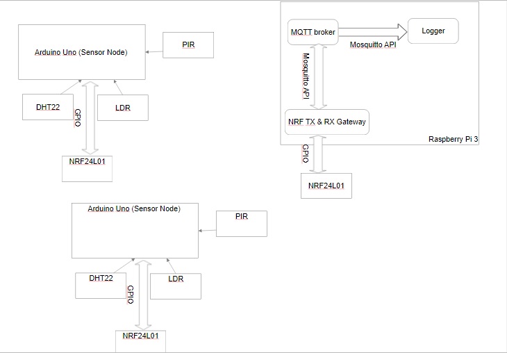
A RF24 network is created with Raspberry Pi as the parent to all the nodes (from now onwards we will call them Knodes). For ease of reference this network will be called ARK network (RF24SN + MQTT along with Knodes}. As of the time of project , there are two child nodes. The Knodes are programmed that they will be delivering the unique message with 5 parameters.
Battery level Temperature Light(%) Humidity PIR-State
The message is sent with sensor values in the variables. The packet when sent from node contains the source and the destination address. Hence, when the header is examined, the message and the routing details can be known. According to this source address, the data is identified to be from which of the nodes it has been sent. Once the node is identified, then the sensor values are read and posted into respective channels in the MQTT broker through mosquitto API to C. The same code contains the section where it is connected to few interested channels. The data from these channels is notified to the program. It is coded to be subscribed to all channels under ‘‘Settings“, with the help of ‘‘#” wild card. Whenever a client publishes data under this channel, it is processed and the equivalent instruction is sent to the sensor node to which it is addressed by the client. For example , If the requirement is such that the interval of measurement for node1 is to be changed to 3 minutes , instead of the current value, then in the following line must be entered in the terminal.
$ mosquitto_pub -t Settings/Knode1/Interval -m 180
Once the above line is executed the data 180 seconds (=3 minutes) is received by the C script and it is sent in its own message structure. The first value is the address to sensor.The second value is the state of the sensor addressed in first value. The third value is the change in interval.
0 0 180
If the Temperature measurement must be switched off, in node1, then the following command is executed in terminal.
$ mosquitto_pub -t Settings/Knode1/Temperature -m Off
1 0 0
where 1- Temperature
2 - Humidity
3 - PIR
4 - LDR
0 - OFF 1 - ON
This particular system is working on push mode. The Knodes are being sent the timing information and hence are pushing the data into the Raspberry Pi. In future, we can also work on pull mode,i.e., data on demand. If monitoring of the system is not required and if the data is needed based on the demand of an external event, this mode can be used. In pull mode, the Knodes will be listening for a command from the Raspberry Pi.It will only measure the required values when instructed. This mode as an option can be integrated into the current system, to make it more versatile.
Advantages of such Standardized system -
-
It is a scalable network.
-
Interoperability between different kinds of nodes is possible.
-
Unified structure and a protocol is being followed.
-
An actuation network can be built anywhere in the network.
Node Red - A Graphical Interface Solution
Node red is an application which is pre-installed in Raspberry Pi. It is a graphical programming tool, which works on Node.js. In Node Red, there are separate nodes modules which have some function associated with it. As soon as a node is executed, the control moves onto the next node module in the flow(the connected diagram in Node red is called a flow). In this way, a complex system can be designed with the help of individual small node modules connected in the way which completes the task.All the nodes start working on being triggered and output the desired function, this data can be used to trigger the next node module.The underlying architecture and communication protocol is similar to that of the previous model.
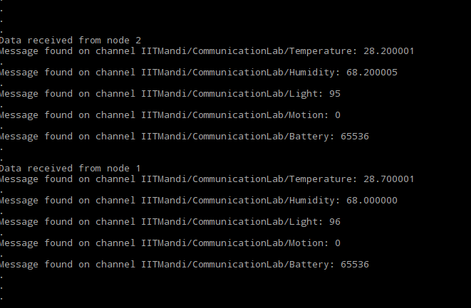
A C script is written such that it receives the data from the NRF radio and prints it onto the command line, in the following format
Node_Number Temperature Humidity Light PIR_State Battery_level
After this execution , Node Red gets call back to the flow with the result. The flow is created such that immediately after receiving the message, it is re-triggered to listen for the next message. In this way, it is in an infinite loop in listening to sensor data.
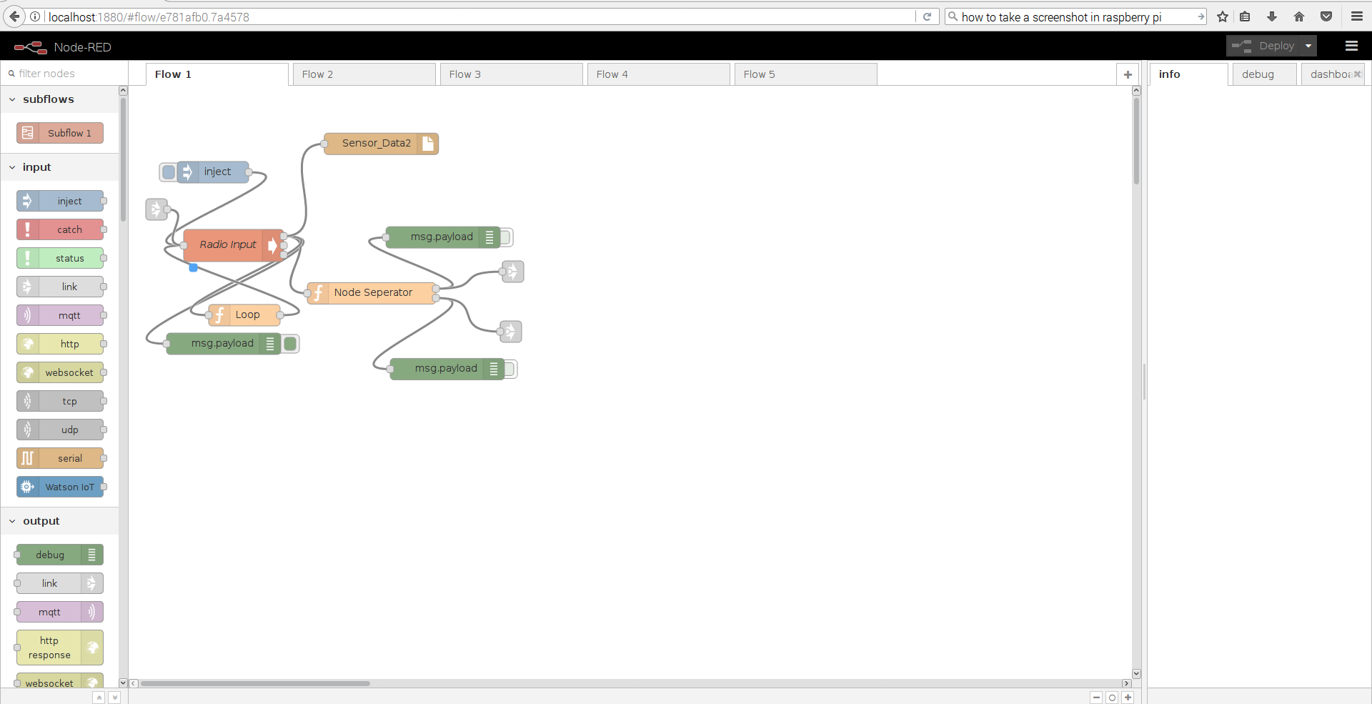
In the Input flow, there is an inject node module which injects a dummy message into the Radio node.On double clicking the node,an option can be seen to inject a message at the start of the deployment.It should be checked for the flow to start immediately after deploying it,else one should click the inject button to start the flow.Radio node is an execution node module in advanced section of the left pane. In this execution node module the following command should be given or a similar one based on the location of the executable script.
$ sudo ./MQTTController (if the file is present in /home/pi directory)
OR
$ sudo ./filepath/MQTTController
The loop node module is a function module found in the left pane. It is a place where a custom script can be executed and the data could be sent as output. The loop node will trigger the Radio node module as soon as receiving the data, thereby keep the forever loop in listening to the data.
The green node in the flow is called debug node, its function is to show the message being passed through the connections in the flows. It is useful for when examining the system in detailed. The debug mode is disabled by clicking the green button attached to it. The “Node separator” is also a custom function node module. This node module is responsible for dividing the incoming data into two paths according to the node that has sent the data.
The grey node modules are linking flows across pages. This is done for aesthetic purposes and to maintain the clarity in the flow diagram.
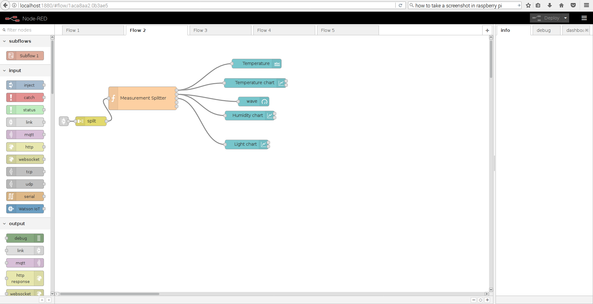
After splitting the data according to the base address, it is sent to the above flow. For explanation purposes, the flow for one sensor node (Arduino board) is shown but exactly similar flow is designed for other sensor nodes (Arduino board) too.
The data is sent from the grey linking nodes. The split node is responsible for splitting the tab spaced data into individual values.For example
2 23.4523 66.9822 89 0 43
into
2
23.4523
66.9822
89
0
43
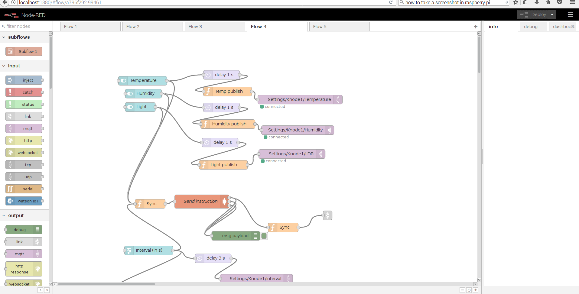
This part of the flow has input from the UI. There are switches integrated into UI for switching an individual measurement between On and Off.Once the state is toggled or the interval of measurement is changed.the node triggers the next node module with the payload.
The node module named Sync sets the Radio variable to Output, in this state, the Radio node in the first flow stops working.It, then starts executing the transmission script which is connected to MQTT broker.
In parallel to this, the code will be delayed by 1 second in the other branch to initiate the transmission script and initialize the radio for it. Then the publish node changes the payload value into an appropriate message for the script to understand. It is then published under the topic in the MQTT broker.
The C script will be waiting for a value to be received via MQTT. Once the value is received, it changes the payload into a format the sensor node understands and send it to the addressed node. The code for the sensor node (Knode) is written such that after every update , it checks if any data is transmitted from the Pi. On receiving the data to the sensor node, it alters the measurement parameters and continues in the new state.The C script in Raspberry Pi will terminate after sending the data. The Sync function is executed which sets the radio value to read mode. This linking node will trigger the reading exec node module in 1st flow.
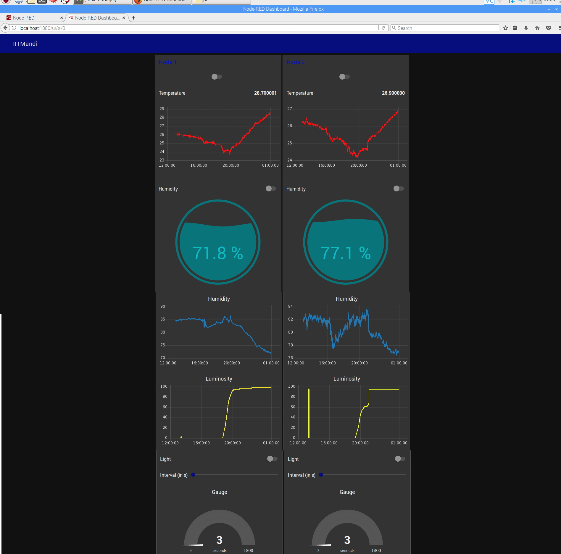
A guage is connected to the slider to show the interval in seconds. The final output in the UI page is
Advantages of using Node Red -
-
Very good GUI is present, which can be used to visualize the data.
-
Easily understandable due to its graphical nature.
-
Little to no programming experience required.
-
If an improvement is required, it can be highly localized to replacing one to two nodes which carry out the specified functionality.
-
It can be used to run bits of code from other languages with the help of exec node which instructs from command line.
Lesson learned and challenges faced
There are quite a few challenges faced while setting up the network.Some of them are -
-
Raspberry Pi was connected to a network which has proxy configured.
-
Int data type, is not of the same size in Raspberry Pi and Arduino and hence when any data is transfered, it was being corrupted at the other end. Instead uint32t as a datatype.
Conclusion and Future scope
In the above ways, a wireless sensor network can be setup for sensing the required parameters. These are first few steps in building a wireless sensor network which is extremely, optimized and streamlined for its use. There are still a few flaws with the current model of network. Working on them will be the future scope of this project.
Some of the flaws in the system are
-
The sleep modes are not effective due to power wastage from power and other LEDs
-
The payload can be reduced by using MQTT-SN structure than MQTT itself.
-
The GUI and communication in Node Red can be further optimized by using a HTTP socket or Serial port communication instead of a call back from terminal.
References
-
Node package manager: Resources for separate node modules.